TA692FC-L – FCU Thermostat Series
Operating Voltage |
230 VAC ±10% |
Measurable range |
0 - 40 °C, 0.1°C |
LoRaWAN |
Class C |
EU868 band |
868.1 MHz ~ 868.5 MHz |
AS923 band (Optional) |
923.2 MHz ~ 923.4 MHz |
Features
Wireless thermostats for fan coil units
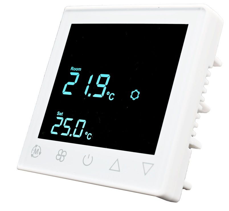
1.5” VA TN with backlit - lite grey text on dark background
Touch keys x 5
Flush-mount installation in an 86 x 86 / British single-gang wall-box
White gloss housing with light grey silk-printed keys
- Controls:
3-speed fan
One DC 0…10V valve actuators
- Used in systems with:
Fan coil units
Heating and cooling appliances
Technical Specification
Transmitting power |
21.0dBm |
Receiving sensitivity |
-140dBm |
Effective range outdoors |
TBD |
Measuring temperature |
0 ~ 40°C |
Controlling temperature |
5 ~ 35°C |
Adjustable span |
1.0°C ~ 4.0°C |
Sensing Element |
103AT |
Storage Temperature |
-5 ~ 50°C |
Measuring accuracy/resolution |
±0.5°C |
On/Off Relay Contact Rating |
230VAC 2(1)A max |
AO Contact Rating |
10VDC 1mA max |
Terminals |
2 mm 2 cable |
Operating Temperature |
0 ~ 50°C |
Operating Voltage |
230VAC ±10% |
Operating Humidity |
5 ~ 95%R.H. non-condensing |
Order Code
Symbols |
Fan Control |
Heating |
Cooling |
LoRa |
Frequnecy |
|---|---|---|---|---|---|
TA692FC-L-1 |
3-Speed |
On/Off heater |
On/Off valve |
LoRoWAN |
endpoint 868.1M~868.5MHz, or 920M~925MHz |
TA692FC-L-2 |
0~10V |
On/Off heater |
On/Off valve |
LoRoWAN |
endpoint 868.1M~868.5MHz, or 920M~925MHz |
TA692FC-L-3 |
0~10V |
On/Off heater |
0~10V modulating |
LoRoWAN |
endpoint 868.1M~868.5MHz, or 920M~925MHz |
TA692FC-L-4 |
0~10V |
0~10V modulating |
0~10V modulating |
LoRoWAN |
endpoint 868.1M~868.5MHz, or 920M~925MHz |
TA692FC-L-5 |
3-Speed |
— |
0~10V modulating |
LoRoWAN |
endpoint 868.1M~868.5MHz, or 920M~925MHz |
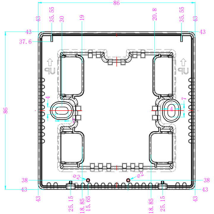
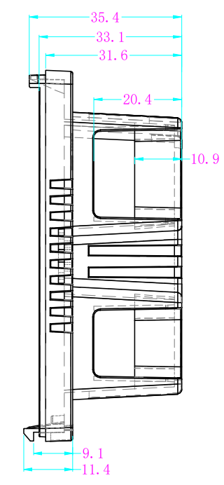
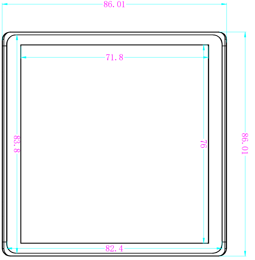
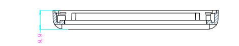
Dimensions / Outline
Protruding part - 86.0mm(W) x 86.0mm(H) x 16.5mm(D)
Concealed part - 64.0mm(W) x 66.5mm(H) x 26.6mm(D)
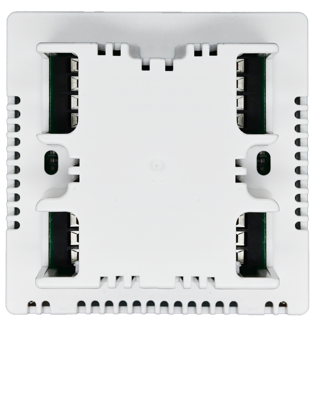
Product pictures

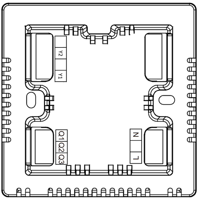
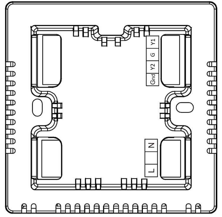
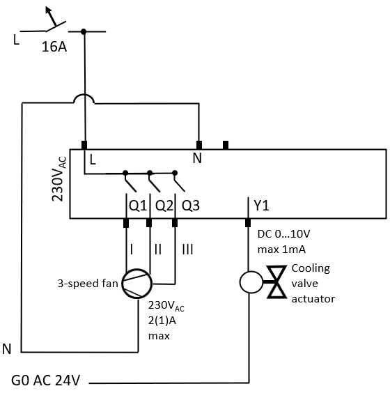
Wiring Example for TA692FC-L-1

Symbols |
Terminals |
|---|---|
L |
Live |
N |
Neutral |
Q1 |
Control output Fan speed 1, 230VAC |
Q2 |
Control output Fan speed 2, 230VAC |
Q3 |
Control output Fan speed 3, 230VAC |
Y1 |
Control output for Cool Valve ON/OFF, 230VAC |
Y2 |
Control output for Heater ON/OFF, 230VAC |
Terminal Labels on TA692FC-L-1
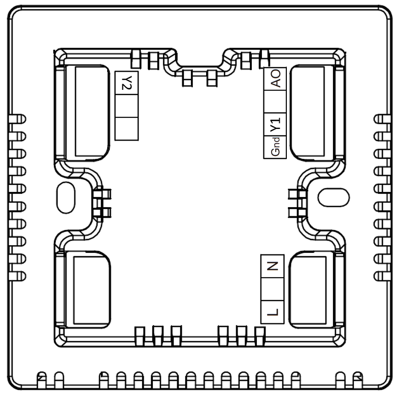
Wiring Example for TA692FC-L-2

Symbols |
Terminals |
|---|---|
L |
Live |
N |
Neutral |
G |
Control output to EC Fan 0…10VDC |
Y1 |
Control output Cool valve ON/OFF. 230VAC |
Y2 |
Control output Heater ON/OFF. 230VAC |
Terminal Labels on TA692FC-L-2

Wiring Example for TA692FC-L-3

Symbols |
Terminals |
|---|---|
L |
Live |
N |
Neutral |
G |
Control output to EC Fan 0…10VDC |
Y1 |
Modulating control to Cool valve 0…10VDC |
Y2 |
Control output Heater ON/OFF. 230VAC |
Terminal Labels on TA692FC-L-3
Wiring Example for TA692FC-L-4

Symbols |
Terminals |
|---|---|
L |
Live |
N |
Neutral |
G |
Control output to EC Fan 0…10VDC |
Y1 |
Modulating control to Cooling valve 0…10VDC |
Y2 |
Modulating control to Heating valve 0…10VDC |
Terminal Labels on TA692FC-L-4
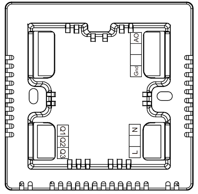
Wiring Example for TA692FC-L-5
Symbols |
Terminals |
|---|---|
L |
Live |
N |
Neutral |
Q1 |
Control output Fan speed 1, 230VAC |
Q2 |
Control output Fan speed 2, 230VAC |
Q3 |
Control output Fan speed 3, 230VAC |
Y1 |
Control output to Cooling valve 0…10VDC |
Terminal Labels on TA692FC-L-5
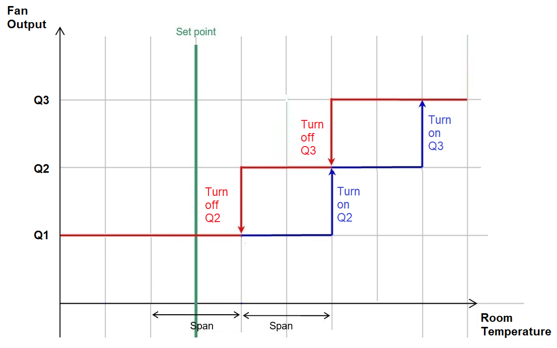
Output diagrams
Fan controls - Q 1 Q 2 Q 3 - in Auto Fan Mode. Applicable to TA692FC-L-1, TA692FC-L-5 Except when Power Off, TA692FC-L is always running at low-fan (Q 1 On).
- Cooling Valve (Y 1)
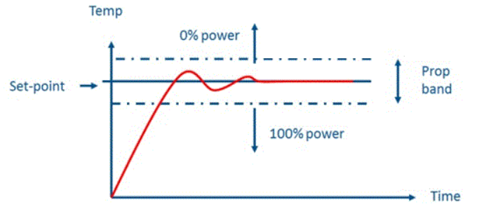
PI control of Cooling Valve (Y 1) in Cool Mode.
Applicable to TA692FC-L-3, TA692FC-L-4, TA692FC-L-5.
TA692FC-L employs proportional-integrative modulating control (PI).
Diagram shows changing in temperature difference versus Y1 voltage level over time.
Ion
 blinks when output power is under 70%; persistently on at 100%; disppears at 0%.
Refer to subsequent sections for K-Factor, P-band and I-time settings.
- Cooling Valve (Y1) in Fan-Only Mode
Applicable to TA692FC-L-3, TA692FC-L-4, TA692FC-L-5.
If Fan-Only Mode is selected, Y1 simply shuts off.
disappears.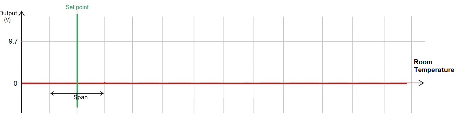
LCD Display Content
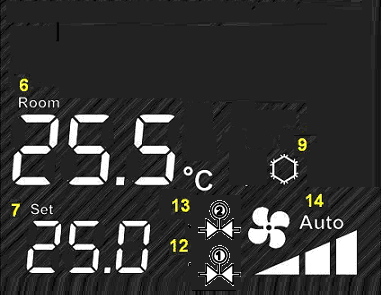
Icons
Label |
Description |
|---|---|
6 |
Room temperature |
7 |
Temperature Setpoint |
9 |
System Mode icon
no icon - Fan-Only mode |
12 |
Y1 output status indicator |
13 |
Y2 output status indicator |
14 |
Fan status indictor
no icon - Manual Fan Mode |
|
High Fan Speed indicator |
|
Med Fan speed indicator |
|
Low Fan speed indicator |
Buttons
Keys |
Function |
|---|---|
|
Menu Key
Short press: change mode
Press-n-hold: Internal setting
|
|
Fan Speed
Short press: cycle-through
L->M->H->Auto->L
|
|
Power On/Off Key |
|
Traverse Up in Setting Menu |
|
Traverse Down in Setting Menu |